
Network Planning / Interactive field guide
PoE Camera Network Planning: Power, Cabling, and Uplinks
Plan a commercial PoE camera network with per-port power checks, switch budgets, cable paths, uplink capacity, backup power, and acceptance testing.
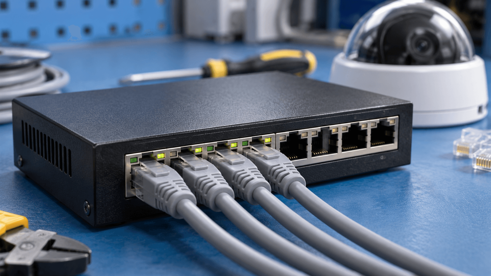
What you’ll leave with
A camera network schedule covering ports, power, paths, uplinks, backup power, and acceptance checks.
- Check each port's capability and the switch's total PoE budget.
- Follow recording and viewing traffic across shared links.
- Include every recording dependency in the backup-power plan.
Power over Ethernet carries network data and power to a compatible camera over the same cable. That simplifies the endpoint connection, but a reliable installation still depends on switch capacity, cable routes, uplinks, and the equipment that records the video. A camera lighting up is only the first check.
Use this guide to prepare an IT and facilities review before adding cameras or replacing a recorder. The same planning method applies to UniFi, Axis, Hanwha Vision, Verkada, and other commercial systems, with model-specific requirements checked in the current datasheets.
Put this guide to work
Check a PoE switch power and port budget
Compare entered camera allocations and other PoE loads with a switch's available budget and your chosen reserve. Per-port standards and uplink capacity are separate checks.
See a worked hypothetical example
These invented inputs demonstrate the calculation. They are not equipment specifications, a recommended design, or a delivery commitment.
- Number of cameras
- 8
- Switch-side PoE allocation per camera (W)
- 15.4
- Other PoE loads on this switch (W)
- 30
- Available switch PoE budget (W)
- 240
- Switch budget to keep in reserve (%)
- 20
- Available compatible ports for these cameras
- 12
8 × 15.4 W + 30 W = 153.2 W planned. 240 W × (1 − 20%) = 192 W available after your reserve. 12 ports are entered for cameras; 4 ports remain.
Keep your project brief
Complete choices above to create a brief. You can copy the guide link now.
Entries stay in this page’s memory. They are not saved to an account or sent in a quote request. Reset or reload clears the tool; downloaded or copied text remains wherever you keep it.
1. Build an endpoint and switch-port schedule
For every camera, record its model, location, PoE standard, maximum power requirement, assigned switch, and port. Include any accessories that draw power. Keep that schedule with the coverage plan so a camera substitution also prompts a power and cabling review.
Axis distinguishes typical consumption from maximum consumption and notes that cable losses affect the power estimate. A daytime measurement with illumination off is therefore a poor sole basis for a switch budget. Use the manufacturer's requirements and the switch's allocation behavior when checking the design.
References
2. Check each port and the total PoE budget
Two separate checks are required: each port must support its connected device, and the switch must have enough total power for all connected loads. Include access readers, wireless access points, or other devices sharing the switch. Confirm which ports provide the needed capability.
Ten devices allocated 12 W each require 120 W before other loads. Reserving 25% of the PoE budget as spare capacity requires 160 W: 120 ÷ 0.75. Use actual switch-side allocations in the calculation; camera-side consumption, cable loss, and negotiated allocations can differ. This reserve is an illustrative planning choice.
| Check | What must pass |
|---|---|
| Per-port capability | The port supports the device's required PoE standard and allocation. |
| Total budget | All planned loads fit the switch's available PoE budget. |
| Expansion | Spare ports and spare power both support the planned additions. |
3. Survey the complete cable path
Measure the actual route, including patching and changes in elevation. Check the cable system against the selected Ethernet and PoE design rather than estimating from a straight line on a floor plan. Document cable rating, termination points, environmental exposure, and any penetrations or restoration work.
For distant cameras, compare a properly designed extension with a fiber link to a nearby powered network location. Extenders have model-specific distance and power limits; they are not an unlimited cure for a long run. Fiber carries the data path, so the remote camera or switch still needs a suitable power source.
4. Follow video traffic to its destination
Draw the path from each camera to its recorder or service and from viewers to the footage. Add expected recording traffic at shared uplinks, then consider live viewing, playback, exports, and other business traffic. Use the chosen platform's network guidance to distinguish local recording traffic from internet traffic.
For example, Verkada documents network connectivity requirements for Command and notes that remote playback consumes upload bandwidth at the camera site. A local-recorder design has different traffic paths. Neither should be sized by multiplying an unrelated marketing bitrate by camera count and assuming the job is complete.
5. Plan outages and network administration
Identify every device that must stay powered to meet the recording requirement: camera switch, upstream switch, recorder, router, or other dependencies. Size backup power using the actual equipment load and the required operating time. Ask how the system behaves when backup power is exhausted and restored.
Have IT approve network separation, allowed connections, time services, updates, and administrative access. A separate camera network still needs the right paths for recording and authorized users. Keep ownership clear so a future firewall or switch change does not unexpectedly remove access to footage.
6. Test the network under representative load
Check recording while multiple users view and export footage. Verify nighttime operation and any high-power camera functions, using the approved test method. Review switch power status, link errors, and recorder health rather than relying only on a successful live image.
- Receive labeled cable results, a port schedule, and an as-installed network diagram.
- Confirm agreed recording behavior during a planned power or connectivity interruption.
- Record remaining port, power, storage, and uplink capacity for the next expansion.
Common questions
Are free switch ports enough for more cameras?
No. Confirm per-port compatibility, total available power, uplink capacity, and recording capacity.
Does a fiber link power a remote camera?
A standard fiber data link does not supply PoE. Plan a suitable power source at the remote camera or switch.
Sources & accuracy notes
Source information reviewed . Confirm compatibility, availability, and commercial terms for the proposed equipment. Planning tools organize your assumptions; the site survey and agreed design establish the final scope.
- Axis: typical and maximum camera power
- Axis: PoE extender range and power requirements
- Verkada: camera network requirements
- Verkada: remote playback and bandwidth
Have a correction or a project question? Contact BlueHouse Telecom.