
Why OTDR testing needs the right launch and receive setup
Plan OTDR launch and receive fibers, endpoint access, compatible connections, and report boundaries before the testing visit.
Quick answer: Plan the launch and receive fibers as part of the OTDR test setup, including their compatibility, suitable length, and access to both endpoints. The test plan should show how the first and last installed connections will be assessed and how temporary test fibers will be distinguished from the installed cable in the results.
A testing visit can reach the far room and discover that nobody arranged access to the final patch panel. It can also arrive with a launch reel that does not match the installed fiber or connector arrangement. Both problems are preventable when the accessories and access plan are reviewed before the appointment.
Launch and receive fibers are easy to overlook because they leave with the testing equipment. Their temporary status does not make them optional details. They help determine what the measurement can reveal about the connections the business will actually use.
Specify the endpoint evidence you expect
Start with the reason the project includes OTDR testing. If the scope requires assessment of both end connections, the setup must support that objective. Merely naming an OTDR model in a proposal does not establish that the first and last interfaces will be evaluated as intended.
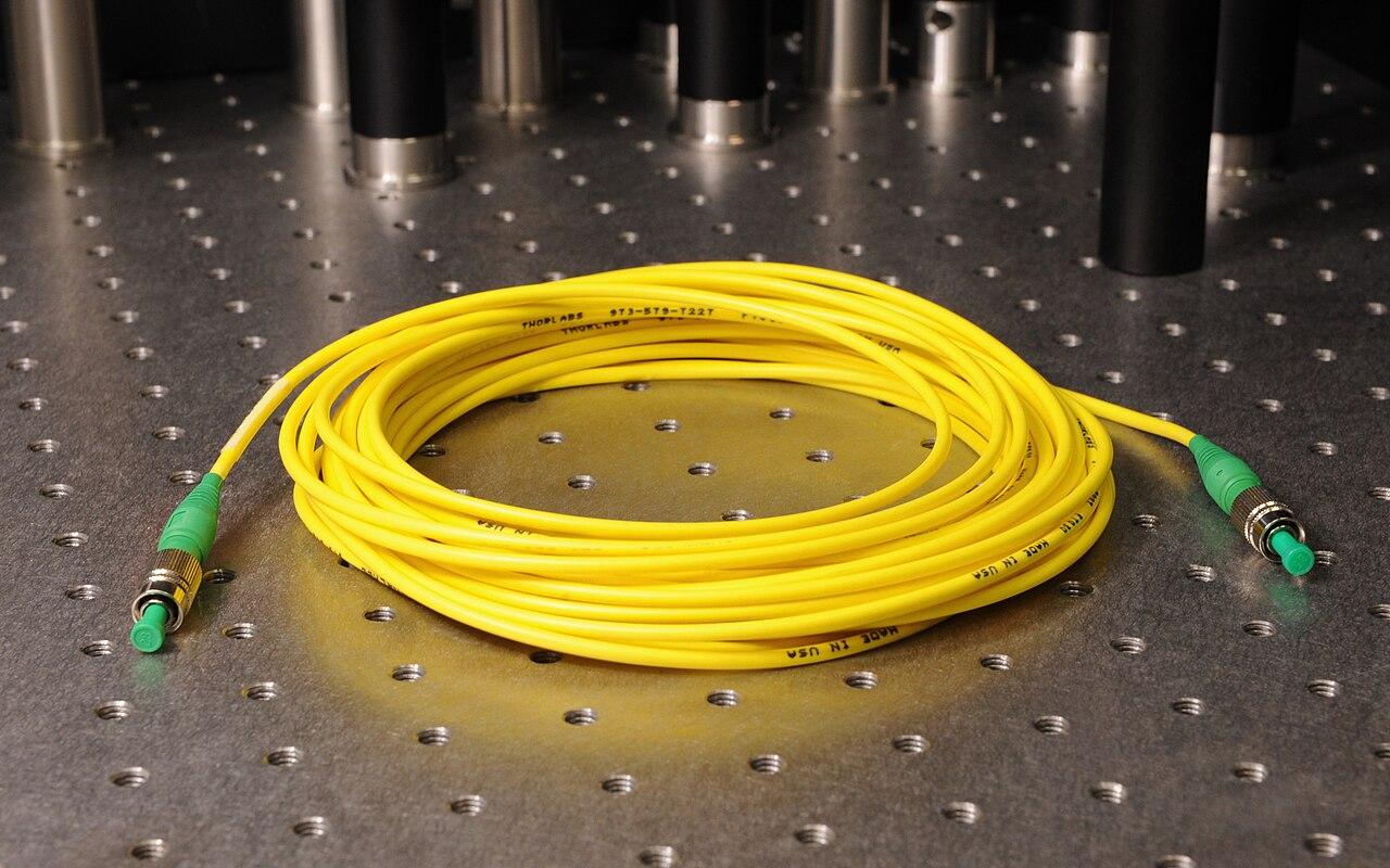
AFL explains that a launch fiber separates the instrument's front-panel effects from the first link connection. A receive fiber provides backscatter beyond the last connection. These are different jobs, which is why a plan for only one end can leave an important question unresolved.
Ask the testing team to show the full arrangement in a simple diagram. It should identify the instrument, launch fiber, installed link, receive fiber, and the connections that define the link boundary. This is a review aid, not an invitation for the owner to improvise connections to live equipment.
The deliverable should describe what was actually tested. If site conditions prevent the planned endpoint assessment, the report should explain the limitation and the required follow-up. A final status should not quietly imply that an inaccessible connection received the same review as the rest of the link.
Match accessories to the specific link
Supply the installed fiber type and the connector details at both ends before the testing visit. Include the physical interface and polish information confirmed from the project documents. A photograph can help identify the location, but color or general appearance alone should not settle compatibility.
AFL specifies matching the test-fiber type to the link under test. The testing team should also verify the instrument and accessory combination for the chosen procedure. Treat that as a complete setup review, not a shopping exercise for a reel with the right-looking connector.
For a hypothetical site with several generations of cabling, one test kit may not cover every link in the same way. Group the planned tests by actual fiber and endpoint configuration. That allows the team to prepare the appropriate accessories without guessing after each panel is opened.
If an adapter or hybrid assembly is proposed, request a clear explanation of where it sits in the setup and how it affects the test boundary. The single-mode versus multimode guide can help organize the inventory before those details are reviewed.
Select length through the measurement requirements
There is no useful universal launch-reel length for every business project. AFL identifies the link, instrument, and network characteristics as factors in the choice. Have the testing team select the arrangement for the actual measurement and manufacturer guidance.
The same caution applies to the receive fiber. Choosing the smallest accessory because it is easier to carry, or the longest because it appears more capable, does not explain whether the required endpoint measurements can be made. Ask for the technical basis without prescribing a number from an unrelated example.
A launch fiber also does not remove every measurement limitation. AFL notes that it does not eliminate the dead zone after the first connection in the link. Closely spaced features may still require careful setup and interpretation by the test operator.
This distinction matters in short building links. The buyer should ask whether the proposed instrument and settings can answer the project question at that scale. If the answer is uncertain, resolve it before using the resulting graph as the basis for acceptance or corrective construction.
Arrange access to the far end as real project work
Put both endpoint locations in the schedule, with an authorized contact for each. Confirm room access, panel access, and any operational restriction on disconnecting the selected fiber. A door badge that opens the building does not necessarily authorize work on the equipment inside it.
Use a preparation checklist that the site coordinator can actually complete:
- Identify the exact near and far panels and strand labels.
- Confirm the approved testing window and affected service state.
- Arrange access and communication between the endpoint locations.
- Verify that required accessories are available for each configuration.
- Define the response if a label, connection, or access condition differs from the plan.
For a hypothetical two-building business, the far endpoint might be inside a tenant-controlled room with different working hours. That access dependency belongs in the schedule before the testing appointment is booked. It should not first become visible when the equipment is already connected at the other building.
Keep production authorization separate from physical access. The responsible network owner should identify which fibers can be disconnected and under what conditions. Avoid assuming that a strand marked spare is available until the inventory and current use have been checked.
Keep the temporary fibers out of the installed-length story
A trace may include the test fibers as well as the cabling being evaluated. The report needs to make that arrangement clear so nobody mistakes a launch reel for additional cable installed in the building. That distinction also matters when a later technician compares records.
Fluke Networks describes launch and tail compensation for separating those test fibers from the link measurement. The operator should follow the supported method and confirm the correct boundary events rather than relying on a guessed length entered after the fact.
Ask for a sample report that shows how the installed start and end are presented. Check whether someone who was absent from the testing visit could understand the boundary. If the export omits that context, agree on an accompanying diagram or explanation before the final package is produced.
Do not use a longer displayed trace as evidence of added installation work. Reconcile measured fiber information with the route and construction records. The commercial quantity, physical route, and test setup are related records, but they should not be collapsed into one unexplained number.
Respond to a questionable endpoint result methodically
If the first or last connection produces an unexpected result, have the testing team investigate the setup and interface under the approved procedure. The temporary accessory can be part of the problem, just as the installed connection can. The result needs diagnosis before the business assigns blame or orders replacement materials.
Keep inspection and handling within the manufacturer's procedure and the site's authorization. The owner should not look into a fiber port or try arbitrary cleaning methods to speed up the visit. Arrange for the responsible team to assess the connection safely with suitable equipment.
Ask the team to explain what changed between measurements. A replacement test accessory, corrected configuration, or physical remediation should be identified. Retaining that information makes the result understandable and prevents a later reviewer from assuming that a cable was repaired when only the setup changed.
If the endpoint remains unresolved, give it a clear disposition. The project may need another access window or a different supported measurement selected by the technical team. Keep that work visible instead of accepting a general report that leaves the original requirement unanswered.
Preserve a repeatable setup for future comparisons
Include the relevant setup information in the closeout package. Record the instrument and configuration, test direction, link identifiers, and launch/receive arrangement needed to interpret the result. The objective is to let a qualified reviewer understand the baseline later, even if a different testing team responds.
Retain the native files and readable reports required by the agreement. A screenshot can be useful during a discussion, but it should not be the sole record when the project calls for a complete test package. Verify that the owner receives files that can be associated with the correct cable inventory.
When comparing a later trace, start by checking whether the test conditions are comparable. Different accessories, settings, or boundaries can complicate interpretation. The maintenance team should explain the comparison rather than treating every visible difference as a new physical fault.
Use the fiber testing acceptance guide to connect this setup record with the other required measurements. Launch and receive planning improves the usefulness of OTDR evidence; it does not independently prove that the complete network or carrier service is ready for use.
The takeaway
The launch and receive arrangement should be planned before the testing team arrives. Confirm compatibility, a technically suitable setup, access to both endpoints, and the way temporary fibers will be separated from the installed link in the report.
That preparation gives endpoint results a clear meaning and reduces avoidable return visits. It also leaves the business with a baseline that can be interpreted during future maintenance, instead of a trace whose boundaries and accessories are unknown.
Include test access in the installation scope
Coordinate endpoints, testing windows, and closeout requirements through BlueHouse Telecom's fiber installation service for a nationwide project plan.
FAQ
Does a launch fiber make every close event visible? No. It helps separate the instrument connection from the first link connection, but it does not eliminate all dead zones or resolution limits. The instrument and setup must suit the measurement.
Why is a receive fiber placed at the far end? It supplies backscatter after the final link connection so that connection can be assessed under the supported procedure. Arrange the necessary far-end access before testing.
Can the same launch reel be used for every fiber type? Do not assume so. The fiber type, interfaces, and instrument requirements must match the specific test arrangement. Have the testing team verify compatibility.
Should test-fiber length appear as installed cable length? The report should distinguish temporary test fibers from the installed link. Use the supported compensation method and clear boundary documentation rather than treating the entire trace as construction quantity.