
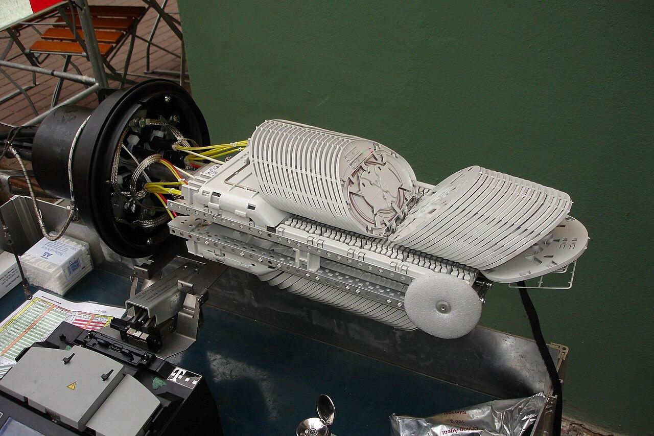
Plan the fiber splice enclosure as part of the cable route
Choose a fiber splice enclosure around cable entries, splice organization, site conditions, and future access instead of capacity alone.
Quick answer: Select a splice enclosure for the actual cables, splice arrangement, environment, and maintenance location. Confirm entry hardware, tray compatibility, fiber storage, and working access before relying on its advertised capacity. The finished design should show how someone can reach a specific splice without unnecessarily disturbing other services.
An enclosure can fit the required number of splices and still be wrong for the job. The cable entries may not match, the trays may support a different splice arrangement, or the chosen mounting location may become inaccessible once the building is occupied.
Treat the enclosure as a working part of the cable route. Its position influences cable lengths, preparation, repair access, and the quality of the records you will need when a connection fails. Those decisions belong in the installation scope before the box arrives.
Locate the enclosure before selecting its capacity
Begin with a marked plan or site photograph showing the proposed mounting point. Identify the cables arriving there and where they continue. A splice location chosen only because it is halfway along a route may be inconvenient or unsuitable for the people who must maintain it.
Check the available working space with the enclosure open, including any removable trays or covers. Consider surrounding equipment, doors, storage, and access restrictions. A location that looks clear during construction may later sit behind a shelf, tenant partition, or active production station.
Ask what a future repair would require. Can the enclosure be serviced in place, or does its design require moving it to a work position? If movement is intended, the cable routing and stored slack must support the manufacturer's procedure. Do not assume that extra cable somewhere nearby makes movement safe.
The fiber installation guide helps establish the physical project boundary. Within that boundary, place the enclosure deliberately and show its access requirements on the drawing rather than leaving its location to an installation-day guess.
Match the entries to the cables
Count cables separately from fibers. Two cables containing many fibers can present a different entry problem from numerous smaller cables with the same combined fiber count. The design must accommodate the actual cable construction and the permitted entry arrangement.
CommScope's closure catalog distinguishes cable sealing types, closure styles, and associated accessories. That matters because an enclosure's headline capacity does not tell you which sealing components or mounting parts are supplied with the specific orderable configuration.
Request the exact bill of materials. Include the closure, entry kits, cable attachment hardware, trays, splice holders, and mounting accessories that the selected design requires. Have the installer confirm the cable dimensions and construction against the applicable product instructions.
The FOA's fusion-splicing guidance directs installers to closure instructions for cable preparation and strength-member arrangements. For an owner, the practical lesson is to avoid generic preparation assumptions. The installed cable must be supported and managed as the selected system requires, not simply pushed through an opening that appears large enough.
Translate the splice plan into the tray arrangement
A maximum splice count is meaningful only with the configuration behind it. CommScope separately identifies single-fusion and mass-fusion capacities and distinguishes tray construction. A number from one configuration should not be borrowed to approve a different arrangement.
Ask how fibers will be grouped. The proposed tray schedule should relate each incoming cable and fiber group to its outgoing destination. That schedule is more useful than a statement that the closure has ample room, particularly when different business services share the same physical location.
Consider a hypothetical campus closure carrying connections to three buildings. Grouping and labeling should let a technician identify the fibers serving one building before opening or moving the relevant tray. The best arrangement depends on the selected products, but the required maintenance task is clear.
Do not confuse unused splice positions with available room for every future addition. A future cable also needs a suitable entry, attachment arrangement, fiber routing, and compatible storage. Capacity planning should identify which future changes the design can support and which would require another enclosure.
Design for the conditions at the mounting point
Describe the actual surroundings rather than labeling the project indoor or outdoor and stopping there. The relevant conditions may include moisture, dust, temperature, chemicals, vibration, or physical contact from nearby activity. Have the designer select components against the requirements that apply at that location.
A building contains different environments. A protected communications room and a washdown area can impose different requirements even though both are under a roof. Similarly, a closure outdoors needs a product and installation arrangement suitable for its particular exposure, not an assumption based on appearance.
Avoid treating a rating printed on the enclosure as permission to ignore the cable entries or mounting instructions. The complete installed configuration matters. Ask how unused entries will be treated and which replacement materials are required if the enclosure is opened for future work.
This is also the time to confirm who can authorize access to the location. A technically suitable position is still a poor operational choice if the business cannot reach it during the hours when an affected service must be restored. Establish the access process without storing sensitive entry details in public drawings.
Review the design with a maintenance scenario
Walk through a specific future task before accepting the layout. For example, ask how a technician would investigate one failed building connection while neighboring links remain in service. The exercise exposes unclear labels and awkward access more effectively than another glance at the product sheet.
Use this checklist during that review:
- Can the enclosure be identified from the route drawing and its physical label?
- Does the cable schedule identify every entry and destination?
- Is each splice group traceable to a tray and position?
- Can the intended tray be accessed using the manufacturer's procedure?
- Are cable support, fiber storage, and service access shown clearly?
- Are required replacement seals or other service materials identified?
- Does the work plan explain how affected services will be protected and checked?
The goal is not to promise that maintenance can always occur without an outage. Some tasks may require a planned interruption. The useful deliverable is an honest explanation of what can be isolated and what would affect other connections.
If the answer requires moving several unrelated fibers just to identify the target, revisit the arrangement. A small change in grouping, labeling, or enclosure location before installation may be easier than living with an avoidable maintenance problem for years.
Connect enclosure records to the test results
A test report needs to identify the physical fibers it describes. Use the same cable and fiber identifiers across the enclosure schedule, patch-panel labels, route drawing, and acceptance records. Otherwise, a passing result may be difficult to associate with the connection someone needs to troubleshoot.
Photographs can help document the completed arrangement, but they should complement readable schedules. Capture useful views without exposing access codes or unrelated customer information. A photograph showing the tray layout is more useful when its filename and caption identify the enclosure and date.
Record the installed configuration, including any approved deviation from the design. If a different tray or entry kit was used, update the component list. The future maintainer needs the parts actually present, not the parts originally proposed in a quote.
Agree on the acceptance tests before the closure work is complete. The fiber testing acceptance guide explains why loss measurements, troubleshooting traces, and physical documentation answer different questions. An orderly enclosure and a passing optical measurement both matter, but neither substitutes for the other.
Include the enclosure in the change process
Every new connection should begin with a capacity and access review. The existence of an empty position is a starting point, not automatic approval to add a cable or splice. Check the selected product's supported configuration and the effect on the existing arrangement.
Keep a short change record that identifies the date, affected fibers, work performed, and updated test references. This does not need to become a complicated software project. It needs to be reliable enough that the next technician can distinguish the current layout from an older photograph.
For a hypothetical warehouse expansion, the original closure may have unused splice capacity but no suitable remaining cable entry for the planned route. Discovering that during design allows a sensible revision. Discovering it after the new cable is installed can force an awkward change to both route and materials.
Before final acceptance, have the installer demonstrate the enclosure identification and the documentation path for one sample connection. The owner should be able to follow it from a business endpoint to the correct cable and fiber record without opening the closure just to guess.
The takeaway
A splice enclosure is useful when its cable entries, trays, mounting position, and records work together. The largest advertised splice capacity does not establish that the selected configuration fits your cable route or future maintenance needs.
Choose the location and splice arrangement first, then confirm the exact product configuration and accessories. Finish with traceable labels, as-built records, and the agreed tests so the enclosure remains understandable after the original installation team has left the site.
Include the enclosure in your fiber scope
BlueHouse Telecom helps businesses plan fiber installation work nationwide, including termination locations, component requirements, and closeout records.
FAQ
Can I choose an enclosure by its maximum splice count? Use that number only with the specified splice type, trays, and accessories. Cable entries, mounting conditions, and working access may limit the suitability of a configuration before its splice positions are full.
Do spare splice positions guarantee room for another cable? No. A new cable also needs a compatible entry, attachment method, and internal routing arrangement. Review all of those requirements before promising future expansion.
Should an enclosure be placed at the shortest cable route? Distance matters, but access and environmental suitability also matter. Compare the full installation and maintenance consequences before choosing the location.
What records should accompany the finished enclosure? Request its location, installed component list, cable-entry schedule, tray and fiber mapping, useful photographs, and linked acceptance results. Keep those records current whenever the splice arrangement changes.