
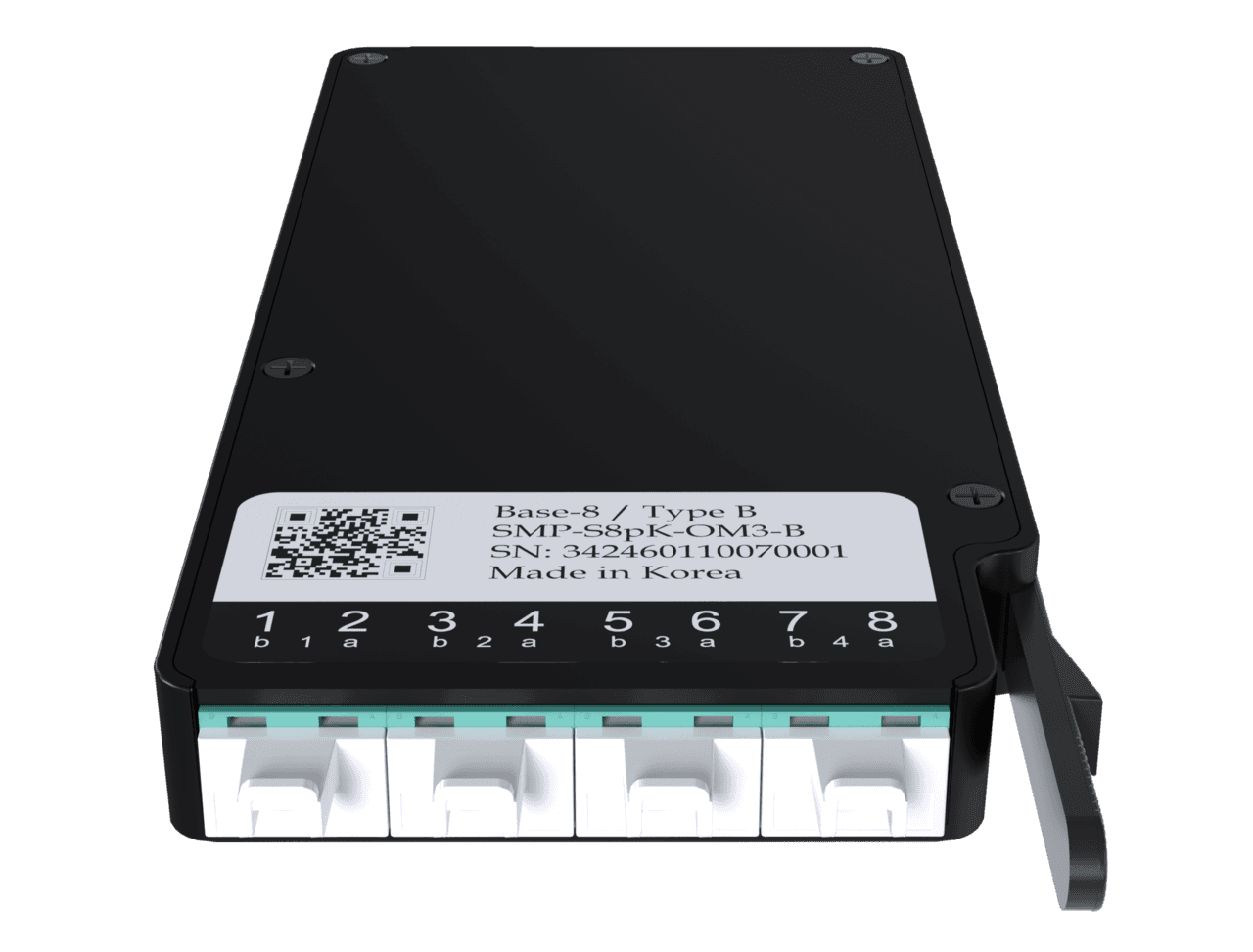
Size a fiber patch panel for the work it must support
Separate fiber counts, adapter openings, splice capacity, and service access when choosing a business fiber patch panel.
Quick answer: Size a fiber patch panel from its complete configuration, not a single port count. Match the number of fibers, connector arrangement, splice requirements, cable entries, and usable rack space. Leave a documented path for the next planned change, including the patch cords and working room needed to make it.
A panel described as having plenty of capacity can be full before its front face looks crowded. The limiting factor may be splice storage, an unavailable adapter module, a congested cable entry, or the space needed to open the enclosure without pulling on live connections.
For a business owner, the useful purchasing question is whether the assembled panel can support the intended links and remain serviceable. That requires a little more detail than a catalog headline, but it is a manageable check during the design review.
Count fibers, interfaces, and links separately
Start with the cables arriving at the rack. List the fiber count in each cable, the fibers to be terminated now, and the fibers reserved for later use. Then describe the optical interfaces the equipment will use. These counts are related, but they are not interchangeable.
A duplex connection uses a pair of fibers in many common arrangements, while other optical interfaces may use different fiber arrangements. Do not convert every fiber count into a fixed number of usable equipment links without confirming the actual optics and design.
Similarly, an adapter-panel opening is a physical position for a compatible component, not necessarily a single fiber or network link. An enclosure with four module openings may support many fibers when populated with the specified components. The opening count alone tells you very little about the final port layout.
Ask the designer to provide a simple count reconciliation. It should show incoming fibers, terminated fibers, populated adapters or cassettes, intended equipment connections, and remaining capacity. This catches misunderstandings before the panel, pigtails, and patch cords are ordered from different assumptions.
Read the configuration behind the maximum
Panduit's fiber splice module specification illustrates why the details matter. Its capacity table separates adapter openings, maximum fiber count, and the capacity of fusion and mechanical splice configurations. Those are distinct columns because they describe different physical arrangements.
For the cited FCE1U enclosure, the document lists four adapter-panel openings and up to 96 fibers. It also lists different maximum splice counts for its specified fusion and mechanical configurations. Those figures describe the documented product combinations; they are not a promise that any mixture of parts will provide the same result.
Use the current manufacturer's documentation for the proposed part numbers. Check which modules, holders, and accessories are included and which must be ordered separately. A compatible enclosure family does not mean every accessory is already present in the shipping carton.
The practical deliverable is an assembled bill of materials that accounts for the planned fiber count. If a supplier changes a component, recheck the configuration rather than approving the substitution because the enclosure still occupies the same number of rack units.
Reserve room for the physical work
A rack elevation shows vertical space, but maintenance needs more than rack-unit arithmetic. Review the enclosure depth, cable entry position, patch-cord exit path, and how covers or drawers operate. Also account for neighboring equipment and the rack door when it is closed.
A sliding enclosure can be convenient only if the installed cable and patch-cord management allow the intended movement. Ask the installer to demonstrate the planned service position using the selected manufacturer's instructions. Do not assume cords can be pulled forward simply because the drawer can.
Access matters at the front and rear. A panel mounted in a shallow wall cabinet may create different constraints from the same panel in an open rack. Existing power equipment, shelves, and cable managers can change how comfortably a technician can reach the relevant components.
Review the business network hardware buying guide when coordinating the panel with switches and other equipment. The passive fiber hardware and active network devices need to fit together as a maintained system, even when they appear on separate purchase orders.
Plan patch-cord movement before the first connection
Dense front panels can save space, but a full patching layout must remain understandable. Decide where cords travel, how destinations are identified, and how a technician will remove one connector without dragging neighboring cords out of position.
Avoid ordering every patch cord at one convenient length. The correct length depends on the actual route through the cable managers and the equipment position. Excess length needs supported storage; insufficient length can make a normal equipment change difficult or encourage an unsuitable shortcut.
Consider a hypothetical rack with an aggregation switch above the fiber panel and access switches below it. Two patching directions may be sensible, but they should be designed deliberately. Crossing every cord over the center of the panel can obscure labels and make later troubleshooting harder.
Ask for a representative patching demonstration before all ports are populated. Verify that labels remain readable, the enclosure operates as intended, and cords follow the selected products' handling requirements. A small adjustment at this stage is easier than reorganizing a fully active rack.
Buy useful expansion capacity
Expansion planning should begin with a plausible next task. A second cable from another floor, more terminated spares, and a new optical interface can consume capacity in different ways. A broad promise of future-proofing does not explain which of those changes the design supports.
Check the following before approving the panel:
- Incoming cable count and the usable entry arrangement.
- Fiber counts and the number to be terminated now.
- Required adapters, cassettes, pigtails, and compatible splice components.
- Front-panel space and the patch-cord management route.
- Access needed to add components or service existing connections.
- The specific future change being reserved for, with its required parts.
A hypothetical business may install a larger cable now but terminate only the fibers required for its first phase. That can be a reasonable design choice, provided the remaining fibers are protected and the records explain what is installed, terminated, and tested. Spare glass is not automatically a ready-to-use port.
Do not buy unused density that complicates today's operation without a credible benefit. The right answer may be a more accessible configuration with a clear expansion path, rather than the highest possible fiber count in the smallest available rack space.
Keep the port map useful to the next person
Labels should connect the front panel to the actual cable and endpoint. A port number that exists only on the panel face is incomplete if the records use a different naming scheme. Agree on identifiers before printing labels or naming test files.
The map should make it possible to trace a connection from equipment port through patch cord, panel, cable fiber, and remote termination. Where cassettes or intermediate connections are involved, include them in the route instead of hiding them behind a generic cable label.
Useful records also distinguish active, available, reserved, and untested positions. These conditions are not the same. Someone planning a new link should not assume a blank-looking port is connected and ready simply because there is no patch cord attached to it.
The FOA's design guidance treats documentation as part of the network project. Apply that principle at the panel by delivering a readable port schedule, a component list, and records of the installed cable routes. Keep a controlled copy where the people maintaining the network can actually find it.
Verify capacity and acceptance in the installed rack
A final inspection should compare the physical panel with the approved configuration. Confirm the installed modules, cable entries, labeling, and organization. If the enclosure differs from the design, require the records to show what changed and why the resulting arrangement remains suitable.
Then review the optical test records against the same fiber identifiers. The fiber testing acceptance guide explains how to define the test boundary and required evidence. A front-panel photograph cannot establish optical performance, and a passing loss result cannot establish that the rack is serviceable.
Have the installer walk through one representative change, such as adding a patch cord to an available terminated pair. The purpose is to check the access and identification process, not to disturb production connections unnecessarily. If the proposed expansion requires additional components, show where they will fit.
Close the project with a clear statement of remaining usable capacity. Include the assumptions behind it: connector arrangement, spare modules, cable entries, and intended future links. That statement is more valuable to the business than repeating the manufacturer's maximum fiber count without context.
The takeaway
A fiber panel has several capacities: it holds components, manages cable and splices, presents connections, and allows people to work. The useful design satisfies all of those needs for the current project and the next realistic change.
Ask for the assembled configuration, a readable port map, and a practical access review. Those checks help prevent a compact-looking purchase from becoming a crowded rack that is difficult to expand or troubleshoot.
Scope a serviceable fiber termination
BlueHouse Telecom helps businesses plan fiber installation projects nationwide, including patch-panel requirements, rack coordination, and test documentation.
FAQ
Does a 96-fiber enclosure provide 96 network links? Not necessarily. The number of usable links depends on the optical interfaces, fiber arrangement, and populated components. Reconcile the fiber count with the actual equipment connections before ordering.
Are spare fibers the same as spare patch-panel ports? No. Fibers may be installed but not terminated, tested, or connected to an available adapter. Document each condition so future work can be priced and scheduled accurately.
Should I always choose the highest-density panel? Choose density that fits the rack and maintenance tasks. A compact panel is useful only when its cable management, access, and component arrangement remain practical for the people supporting it.
What should the final capacity record include? Identify populated modules, terminated and tested fibers, unused entries, remaining compatible component positions, and the expansion scenario those resources support. State the assumptions instead of listing only a maximum number.