
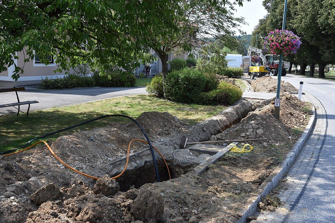
Planning Fiber Between Two Business Buildings
Plan a building-to-building fiber link from the required applications through routes, endpoints, optics, testing, and support.
Quick answer: Design a connection between buildings as a complete network link, including the physical route and the equipment at both ends. Confirm ownership, application requirements, suitable fiber and optics, and the power and environmental needs of the endpoint equipment. Accept the cable with the agreed optical tests and the business connection with representative application checks.
Two nearby buildings can require a surprisingly substantial connection project. The visible distance across the yard leaves out the route into each building, the equipment room locations, and the network decisions that let staff use the link. A cable price alone gives the owner an incomplete picture.
Begin with the reason the buildings need to communicate. A hypothetical company connecting an office to a warehouse may need business applications, local printing, cameras, or wireless infrastructure in the second building. Those requirements should shape the design before the project settles on a cable count or a switch model.
Define the work that crosses between buildings
List the applications and device groups that need the connection, then identify where the relevant services operate. A warehouse task using a server in the office differs from a task that only needs internet access. The network designer needs that distinction to propose the appropriate relationship between the buildings.
Ask which activities must continue during an interruption and which can wait. Avoid treating every connected device as equally urgent. The business may prioritize dispatch transactions while accepting that a large file transfer can resume later. That decision helps define the required capacity and continuity discussion without inventing a universal design.
Include the intended network boundaries. Connecting two buildings does not mean every device should have unrestricted access to every other device. Have the responsible network and security team define the permitted communication, then make those requirements part of configuration and acceptance rather than leaving them to default equipment settings.
Trace the route from termination to termination
Measure the proposed path between the actual termination locations. Include outdoor routing, building entrances, vertical sections, and the cable management required by the design. The straight-line distance on a map is useful orientation, but it is not the complete installed cable length.
The FOA design guidance emphasizes the actual route and its effect on installation choices. An existing duct or apparent aerial path needs assessment of ownership, condition, access, and suitability. Ask the survey to identify what has been verified and what remains an assumption in the proposed price.
Where several routes are possible, compare the whole path and its operating implications. A slightly longer route might avoid a difficult entrance or improve maintenance access. Let the qualified designer evaluate the tradeoff rather than choosing the shortest line before the building and infrastructure owners have reviewed it.
Establish the endpoints as real installation locations
Identify where the fiber terminates and where the active network equipment will operate at each building. Confirm the approved space, access, power, environmental conditions, and equipment mounting arrangements with the responsible specialists. An empty wall near the entrance is not automatically a suitable network location.
Ask how the endpoint equipment will be supported during ordinary maintenance and a power interruption. Optical fiber carries the communication path, but the switches and connected systems still need their designed power arrangements. A fiber cable between buildings does not by itself keep equipment operating when either endpoint loses power.
Keep any electrical, bonding, structural, or building-protection requirements within the qualified design scope. Cable construction and site conditions matter, and the buyer should not infer the required treatment from the word fiber. The proposal should identify the necessary professional review and include the resulting work at the appropriate boundary.
Select fiber and optics as a matched link
Have the designer identify the proposed fiber type, connector arrangement, optical modules, and supported switch ports at both ends. Physical fit is not the complete compatibility test. The selected components must support the intended application over the designed installed link, including its connections and losses.
Cisco's current 10GBASE SFP+ data sheet, for example, lists different fiber media and reach conditions for different modules and provides platform-support information. That demonstrates why an SFP+ label alone is insufficient. Check the exact module and host support rather than assuming any two modules with the same form factor form a suitable pair.
The single-mode versus multimode guide can help frame the purchase discussion. Avoid choosing only by a familiar cable color or a generic distance rule. Ask for the documented basis of the selected link and what would need to change if the required speed or endpoint equipment changes later.
Make the boundaries of the quote visible
Request a proposal that follows the connection through both buildings. It should distinguish cable and pathway work from active equipment, configuration, and application acceptance. All of those tasks may be required even when they appear in different purchasing documents or belong to different internal owners.
Use a short completeness check:
- Both termination locations and the approved physical route are identified.
- Cable, terminations, optical modules, and supported endpoint equipment are assigned.
- Building preparations, permissions, and affected-site restoration are covered.
- Testing, network configuration, application checks, and final records have defined owners.
I would rather see a clear exclusion than a broad promise to connect the buildings. An exclusion tells the buyer what remains to arrange. A vague promise can conceal an assumption that someone else will provide the switch, configure the network, or approve the building entry after installation has already started.
Schedule the change around both operations
Ask the teams in both buildings when the work can occur and who can participate in acceptance. The office may be quiet while the warehouse is dispatching orders, or the reverse. A window selected from one manager's calendar can overlook the operation that has the least flexibility.
If the project replaces an existing connection, have the technical owner define the migration and recovery approach. Preserve the evidence and configuration needed for that plan through the business's approved process. Do not disconnect a working path just because the new cable has arrived on site.
Include preparations that can be completed before the change window. Termination work, equipment readiness, and agreed tests may have dependencies that should be resolved earlier. The project team should distinguish ready to install from ready to move production traffic, so scheduling pressure does not collapse those stages into one assumption.
Accept the optical link and the business task
Agree on the cable test scope before installation, including link identifiers, test methods, limits, and the records delivered. The fiber testing acceptance guide explains the buyer's review of those results. A device link light is useful operational evidence, but it is not a substitute for the specified cable acceptance.
After the physical link is accepted and the approved configuration is applied, test the tasks that justified the connection. Have authorized users complete representative transactions or device workflows with approved test data. The required result should be defined by the relevant application owner, not inferred from successful web browsing.
For a hypothetical warehouse link, the test might include retrieving a work item, printing an approved sample label, and confirming the expected camera or access-point connectivity where those systems are in scope. These are examples of business checks, not claims that every warehouse uses the same equipment or requires the same network design.
Record unresolved findings separately from successful tests. If the cable meets its acceptance requirements but an application remains unavailable, retain both facts. They guide different investigations and prevent the entire project from being described either as a complete failure or as fully finished without evidence.
Decide what the next connection will require
Ask what an additional building or increased workload would need. Spare fibers may help one expansion while a new endpoint location requires another pathway. Separate those possibilities and request an explanation of which future use the current design can reasonably accommodate.
Discuss continuity using actual physical and equipment dependencies. Another strand in the same cable does not avoid a cable cut, and another cable along the same route can still share exposure. The appropriate specialists should assess the business requirement before describing an arrangement as redundant or diverse.
At handover, retain route information, termination identifiers, accepted component details, test results, and the approved support contacts. Keep sensitive management information in the proper controlled system. A future technician should be able to understand the connection without relying on the memory of the person who originally ordered it.
For a nationwide property portfolio, use a common project checklist but preserve each site's evidence. Distances, buildings, ownership, and operating needs can differ substantially. Consistent questions help the company compare projects; a repeated bill of materials does not prove that every property needs the same design.
The takeaway
A building-to-building fiber project connects equipment, applications, and operations through a physical route. Establish the endpoints and permitted communication first, then have the qualified team specify the cable, optics, supporting infrastructure, and acceptance evidence. The visible space between buildings is only one part of the scope.
Test both the defined optical link and the business work it serves. Keep the results and future expansion assumptions with the final records. That gives the owner a connection that is understood and supportable, with clear limits on what the project has actually demonstrated.
Plan the link between your buildings
Request a BlueHouse Telecom fiber installation consultation with the building locations, required applications, and available route information.
FAQ
Is the distance between building walls enough to order the cable? No. The design needs the actual route between termination locations, including entrances, interior sections, and required cable management. Have the survey establish the installation length and method.
Does fiber provide power to the switch in the second building? An ordinary optical fiber link does not replace the endpoint equipment's power arrangement. The design must provide appropriate power for switches and connected systems at each location.
Can any two SFP+ modules be used for the link? No. Verify the exact modules, host support, fiber media, optical limits, and intended application. A matching physical form factor is only one part of compatibility.
Does a spare strand provide a backup route? It provides another strand within the same cable. A cable failure or shared physical event can affect it too, so any continuity claim needs assessment of the actual routes and equipment dependencies.